


PS2 Joystick Module
15 in stock
- Dimensions: 34 x 34 x 15 (LxWxH) mm.
- Weight: 10gm (without Hat).
- 2.54mm pin interface leads.
- Operating Voltage: 5V.
- Long service life and stable performance.
- Standard interface and electronic building blocks.
- Widely use in Arduino DIY projects.
₹50.00 ₹75.00
15 in stock
CompareA PS2 game joystick module is an input device commonly used in electronic projects and DIY applications to provide analog control over various systems. It resembles the traditional joystick found on gaming consoles and is designed to translate physical movement into electrical signals that can be processed by microcontrollers, computers, or other electronic devices.
The ps2 joystick module typically consists of the following components:
Joystick Mechanism The main component is the physical joystick mechanism, which allows users to move the stick in different directions. It usually has two axes of movement: the X-axis (left-right) and the Y-axis (up-down). Some joystick modules also come with additional buttons for extra functionality.
Variable Resistors (Potentiometers) Within the joystick’s base, there are two variable resistors (potentiometers) – one for each axis. These resistors change their resistance values based on the position of the joystick in the X and Y directions.
Analog Output The varying resistance of the potentiometers generates analog voltage signals proportional to the joystick’s position on each axis. For example, when the joystick is centered, the resistance and voltage output are at a midpoint. As the joystick is moved in any direction, the resistance and voltage output change accordingly.
InterfaceThe PS2 game joystick module often has pins or connectors that allow easy interfacing with microcontrollers or other electronic circuits. The outputs may be in the form of analog voltages, making them compatible with ADC (Analog-to-Digital Converter) inputs on microcontrollers.
Applications
- As square wave signal generator which generates a square wave signalTo provide a signal to the stepping motor driver
- Adjustable pulse generation for chip use
- Produce variable pulse signal, the control-related circuit (PWM dimming, speed)
Module Description
- XXX (no decimal point):the smallest unit is 1Hz,the range 1Hz-999Hz
- XX.X (decimal point in ten): The minimum unit is 0.1Khz; the range of 0.1KHz-99.9KHz
- X.X.X.(there is three decimal point): the smallest unit is 1Khz; the range 1KHz-150KHz
- ”100″ indicates that the PWM output pulse of 100Hz
- ”54.1″ indicates that the PWM output pulse of 54.1KHz
- ”1.2.4.” Indicates that the PWM pulse output 124KHz
- Duty Cycle in the range:0 to 100
- Three frequencies duty cycle is the same, all the parameters non-volatile
- 2.54mm pin interface leads
- Long service life and stable performance
- Standard interface and electronic building blocks
- Widely use in Arduino DIY projects
- Cross rocker as a two-way 10K resistor, with the rocker in a different direction.
requency is divided into three ranges:
Frequency Display Example
Features
Package Includes
- 1 x joystick module
Based on 0 reviews
Be the first to review “PS2 Joystick Module”
You may also like…
Related products
-
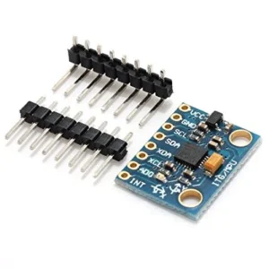
ACCELEROMETER & GYROSCOPE, SENSOR AND MODULES
MPU-6050 3-Axis Accelerometer and Gyro Sensor
Features :
- Chip built-in 16bit AD converter, 16-bit data output.
- I2C Digital-output of 6 or 9-axis MotionFusion data in rotation matrix, quaternion, Euler Angle, or raw data format.
- Selectable Solder Jumpers on CLK, FSYNC, and AD0.
- Digital Motion Processing™ (DMP™) engine offloads complex MotionFusion, sensor timing synchronization, and gesture detection.
- Embedded algorithms for run-time bias and compass calibration. No user intervention is required.
- Digital-output temperature sensor.
Driver IC MPU-6050 Operating Voltage (VDC) 3 ~ 5 Communication I2C Protocol Gyro range(°/s) ± 250, 500, 1000, 2000 Acceleration range(g) ± 2 ± 4 ± 8 ± 16 Length (mm) 20 Width (mm) 16 SKU: n/a -
SENSOR AND MODULES
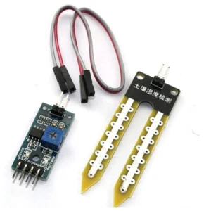
Soil Moisture Meter, Soil Humidity Sensor, Water Sensor, Soil Hygrometer for Ardunio Rated 4.50 out of 5 based on 2customer ratings (2 customer reviews)
 SENSOR AND MODULES
Soil Moisture Meter, Soil Humidity Sensor, Water Sensor, Soil Hygrometer for Ardunio Rated 4.50 out of 5 based on 2customer ratings (2 customer reviews)
- Dual output mode, analog output more accurate
- A fixed bolt hole for easy installation
- With power indicator (red) and digital switching output indicator (green)
- Having LM393 comparator chip, stable.
- Operating Voltage: 3.3V~5V
Soil Probe Dimension Approx. 6cm x 3cm Cable Length (cm) 20 Shipping Weight 0.02 kg Shipping Dimensions 8 × 6 × 3 cm SKU: n/a -
ACCELEROMETER & GYROSCOPE, SENSOR AND MODULES
ADXL335 Module 3-axis Analog Output Accelerometer
Features :
- Onboard LDO Voltage regulator
- Can be interfaced with a 3V3 or 5V Microcontroller.
- All necessary Components are populated.
- Ultra-Low Power: 40uA in measurement mode, 0.1uA in standby@ 2.5V
- Tap/Double Tap Detection
- Free-Fall Detection
Operating Temperature (°C) -40 to 90 Length (mm) 21 Width (mm) 16 Height (mm) 2.5 Weight (gm) 0.6 - Analog output
- Build-in ultra-low noise linear LDO voltage regulator
- Built-in onboard filters, which reduce noise from the motor and other high current electronics
- Power LED
- Designed for 5V logic level
SKU: n/a -
GSM and GPS Modules, SENSOR AND MODULES
NEO-6M GPS Module with EPROM
- 5Hz position update rate.
- The cold start time of 38 s and Hot start time of 1 s.
- Configurable from 4800 Baud to 115200 Baud rates. (default 9600).
- SuperSense ® Indoor GPS: -162 dBm tracking sensitivity.
- Support SBAS (WAAS, EGNOS, MSAS, GAGAN).
- Separated 18 x 18mm GPS antenna.
Model Ublox NEO-6M Receiver Type 50 Channels, GPS L1 frequency, C/A Code, SBAS: WAAS, EGNOS, MSAS Input Supply Voltage (VDC) 2.7 ~ 6 Main Chip NEO-6 Sensitivity (dBm) -160, 156, Cold Start (without aiding): -147 dBm, Tracking & Navigation: -161 dBm Navigation Update Rate 5Hz Position Accuracy (Meter) 2 Operating Temperature Range (°C) -24 to 84 Tracking Sensitivity (dBm) -161 dBm Avg Cold Start Time (s) 27 Warm Start Time (s) 27 Maximum Speed 500 M/s Dimensions (mm) LxWxH Antenna – 25 x 25 x 7, GPS Board – 22 x 30 x 4 Weight (gm) 12 Cable Length (cm) 10 Shipping Weight 0.016 kg Shipping Dimensions 8 × 6 × 4 cm SKU: PH010


There are no reviews yet.